If a person brings in a personal computer and decides to connect it to your network, they could go to his or her personal email and potentially infect your network with any number of malicious viruses. By implementing a transparent proxy, he or she is redirected to the proxy like any corporate machine. Instead of implementing the proxy under the browser settings, transparent settings are configured on the upstream router via WCCP (web cache communication protocol).
What about CDA (Context Directory Agent), what does that do? As you'll see in the WSA logs..everything is based off IP address. If person X goes to www.badhackerviruswormsite.com....how do we track down the user to drop the hammer? We COULD take the IP address and track it out in the most traditional senses (IP X maps to MAC X, and MAC X was learned on port X......trace cable....) but that is a huge pain in the butt! CDA allows you to integrate with active directory to create an IP to username mapping! Instead of seeing 10.0.20.32 in logs..you'd see first.last (or whatever your naming scheme is). Technically, the WSA will interact with the CDA using RADIUS in order to obtain the latest set of IP-to-user identity mappings.
Furthermore,the CDA eliminates the need for NTLM authentication. Once a user logs onto their computer in the morning and authenticates to the domain, the CDA will have received a successful audit event/log that informs it that user X is signed on to IP address X. When the WSA needs to find out who is on this IP address, instead of using NTLM to challenge the client machine, it will ask the CDA who signed on this particular IP address. Once it gets the user name, the WSA will proceed as usual and query the AD to determine the group membership of that particular user.
Some of this will be in my lab environment and the rest will be what I've captured in a production environment. For testing purposes..I can only do SO much, as I don't have active directory in my home network (weak, I know). **As you'll see later on I got tired of the testing limitations and went ahead and deployed AD on my home network---Cool I know**
Here is a brief overview of what we're trying to accomplish (thank you Cisco for the pretty diagram!):

This example uses an ASA as the redirect..but you can do it on any number of devices that support WCCP (so yea, a Cisco router).
Before ANY traffic is redirected, WCCP communication needs to occur between the redirecting device and the WSA:
1. WSA sends "Here I am" messages to the IP address configured in the transparent redirect configuration settings using UDP port 2048.


Now that WCCP has formed an adjacency with the firewall and the WSA, the firewall will inspect traffic on the configured redirect interface for anything with a destination port 80 (web-cache). The next section will discuss what happens if the destination port is 80!
This is what you'll see (a packet capture right off a production WSA with a user going to www.purple.com):
- Computer (172.26.63.252) sends TCP SYN packet to www.purple.com (153.104.63.227)
- Firewall intercepts the TCP SYN and encapsulates the packet with GRE and forwards it to the WSA. The ASA uses its WCCP router ID as the source (192.168.80.4) with a destination of the WSA P1 interface (172.21.54.150). The WCCP router ID is automatically identified as the highest IP address. It will use the highest loopback IP address (not applicable in this case) as the router ID if one is present.
- WSA responds back to computer with a syn-ack, spoofing the source as the intended destination (purple.com)
- Computer sends an ACK to www.purple.com (to complete the 3-way handshake.
- ASA intercepts the ACK packet and forwards this to the WSA (Encapsulated via GRE).
- 3-way handshake COMPLETE!
- Computer sends HTTP GET to purple.com
- ASA intercepts the HTTP GET packet and forwards this to the WSA (Encapsulated via GRE).
- WSA sends an ACK to the computer, again spoofing the source.
- WSA establishes a new connection from its IP (172.21.54.150) with the remote server and gets HTTP data. We see the destination as the CWS tower in this scenario.
- WSA starts sending the HTTP content to the initiating computer.
907
25.570827 172.26.63.252
153.104.63.227
TCP
94 2518→80 [SYN] Seq=0 Win=8192
Len=0 MSS=1366 WS=256 SACK_PERM=1 (2)

908 25.570936 153.104.63.227 172.26.63.252 TCP 66 80→2518 [SYN, ACK] Seq=0 Ack=1 Win=64000 Len=0 MSS=1366 WS=64 SACK_PERM=1 (3)
909
25.573495
172.26.63.252
153.104.63.227
TCP
82 2518→80 [ACK] Seq=1 Ack=1
Win=16384 Len=0 (5)
910
25.573772
172.26.63.252
153.104.63.227
HTTP 351 GET /
HTTP/1.1 (8)
911
25.573840 153.104.63.227
172.26.63.252
TCP 54
80→2518 [ACK] Seq=1 Ack=270 Win=63680 Len=0 (9)
912
25.576083
172.21.54.150
108.171.132.132
TCP
74 40591→8080 [SYN] Seq=0
Win=12288 Len=0 MSS=1460 WS=64 SACK_PERM=1 TSval=588501272 TSecr=0 (10)
913
25.594294
108.171.132.132
172.21.54.150 TCP
66 8080→40591 [SYN, ACK] Seq=0
Ack=1 Win=14600 Len=0 MSS=1380 SACK_PERM=1 WS=128 (10)
914
25.594348
172.21.54.150
108.171.132.132
TCP
54 40591→8080 [ACK] Seq=1 Ack=1
Win=12416 Len=0 (10)
915
25.594574
172.21.54.150
108.171.132.132
HTTP 1123 GET http://www.purple.com/ HTTP/1.1 (10)
916
25.612931
108.171.132.132
172.21.54.150 TCP
60 8080→40591 [ACK] Seq=1
Ack=1070 Win=16768 Len=0 (10)
917
25.681801
108.171.132.132
172.21.54.150 TCP
60 8080→4621 [RST, ACK]
Seq=1845 Ack=1668 Win=270 Len=0 (10)
918
25.711278
108.171.132.132
172.21.54.150 TCP
287 [TCP segment of a reassembled PDU] (10)
919
25.711327
172.21.54.150
108.171.132.132
TCP
54 40591→8080 [ACK] Seq=1070
Ack=234 Win=12160 Len=0 (10)
920
25.711660
108.171.132.132
172.21.54.150 HTTP
1261 HTTP/1.1 200 OK (text/html) (10)
921
25.711699
172.21.54.150
108.171.132.132
TCP
54 40591→8080 [ACK] Seq=1070
Ack=1441 Win=11200 Len=0 (10)
922
25.711805 153.104.63.227
172.26.63.252
TCP 1420 [TCP
segment of a reassembled PDU] (11)
923
25.711815 153.104.63.227
172.26.63.252
HTTP 203 HTTP/1.1
200 OK (text/html) (11)
924
25.715453
172.26.63.252
153.104.63.227
TCP
82 2518→80 [ACK] Seq=270
Ack=1516 Win=16384 Len=0 (11)
Wait a second..what the hell is 108.171.132.132? In this particular scenario we're using the WSA as a connector to Cisco's Cloud Web Security. If using the WSA as a stand-alone device, you'd see the destination as the website (purple.com).
LESSONS LEARNED:
- DO NOT HAVE MULTIPLE ROUTER IPs FOR DIFFERENT DEVICES--THIS DID NOT WORK!
- IF you use multiple service groups, it WILL failover..but it will NOT fail back.
In my lab environment I'm running 2 ESXi 6 hosts and a 2811 router.
To start, lets get the WSAs deployed. Cisco makes this super easy by using OVFs!

Here are the recommended hardware specs for the VMs we'll be deploying. For lab purposes, I'll be using the S000v.
In addition, here is the CVD for deploying WSA.
Also, here is a useful blog for deploying WCCP on a 6500.
First off, when you download the zip file from Cisco...we really only care about the .ovf file inside.

When you start deploying the OVF you'll get prompted with the usual parameters of which host and datastore to run the VM. In addition, you'll get prompted with what hostname you wish to give the system and what networks to use. The device has 5 configurable interfaces: M1 for management, P1/P2 for data, and T1/T2 for L4 traffic monitoring. In my lab I put the management interface on my "management" dvswitch and the rest on my "vm traffic" dvswitch. This can all be changed after the OVF has been deployed.
Once you've finished deploying the OVF and its powered on, you can log into the device with the username admin and the password ironport.
Once logged in, you have a couple of parameters that are worth configuring. By default the management IP address is allocated via DHCP. If you wish to statically configure an IP address, use the command "INTERFACECONFIG" to modify the management port.

Note: I've already configured this appliance...hence why you see the P1 interface and the hostname. Once you EDIT the interface, you'll need to perform a "COMMIT" for the changes to stick.
One more helpful command is "SETGATEWAY" as this will allow you to change the gateway to one different than allocated from DHCP (should you care).
Once everything has been configured, you should be able to navigate to the device via "https://<ip address>:8443"
Once you log in..you'll find that the features are QUITE limited. The feature set is limited until you apply a license. For my lab environment, I simply used an evaluation license (good for 45 days).
Go here to get a license or download an evaluation license!
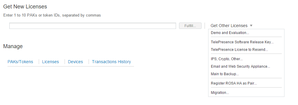
For evaluation purposes...click on the "Demo and Evaluations" link.
Once you've downloaded the license, the method of applying the license is via the CLI (copy and paste) or via FTP. I decided to use the second method.
1. Enable FTP (via the interfaceconfig command)
2. Log in using the credentials admin/ironport.
3. Copy the license file to the configuration folder (using the name license.lic
4. Press enter in the CLI (if you renamed it you should only need to press enter).
You'll have to accept the user agreement and you'll be good to go!
NOTE: If the license fails with a reason of "Not yet ready" or something of the sorts...VERIFY the time/date...in my case the date was wrong so it would not accept the license! Perform a "DATE" command to show the time/date. If you wish to change it, use "SETTIME."
Once logged in, you'll want to do the following:

1. Apply any feature keys that have not been applied.
2. Perform any system upgrades.
3. Perform the system setup wizard.
The one thing worth noting is that during the system setup wizard, I selected the box in the interface configuration to ONLY use M1 for management purposes. I want all my data traffic to go through the P1 interface.
I did ALL of this a second time so that I have two virtual appliances.
For network redundancy purposes, you can navigate to network->high availability and configure VRRP. In my scenario I created two failover groups: One for management and one for data. My first vWSA is the primary for both the management and the data. This is accomplished by giving the failover group a higher priority (255 in this case).
One thing worth mentioning is that promiscuous mode on the dvswitch MUST be enabled for this to work!

At this point...we should be able to a basic test. Under your internet options->connections->lan settings...configure the proxy settings to point to the P1 interface VIP using port 3128. We don't have any rules yet...so our test will be to simply go to www.not-a-site.com. Since this will not resolve, you should get an error back looking like the following:

Yay, the proxy is blocking this since it won't resolve externally. Without the proxy, you'd normally see an error like "This webpage is not available."
This is NOT transparent mode...as we had to configure the browser to point to the WSA. To configure the WSA to support WCCP...we first have to create some transparent redirection rules.

The first thing we need to do is change the transparent redirection device from L4 switch to WCCP v2 Router.
Once this is done we'll create the WCCP v2 services. In my lab environment I've created the following services pointing to the router IP address that we wish to proxy. In this example it is 10.0.100.1, which is the SVI and gateway for my wireless users.

Now we're ready to make the changes on the Cisco router!
Since I'm currently only providing proxy services for my wireless users, the configuration is as follows:
config t
ip access-list extended ACL_WCCP
!This says proxy everything! Use a deny statement to exempt a subnet.
permit ip any any
ip wccp version 2
ip wccp web-cache redirect-list ACL_WCCP
!
interface vlan 200
ip wccp web-cache redirect in
!
The WSA will communicate with the router IP address specified in the WCCP services!


Now that the router sees the WSA..lets create a basic rule to test! I'm going to create a custom URL category to test on my home network. This section is found under web security manager->custom URL categories. I created a URL category called "Drop list" that contains the URL "www.cnn.com" as a test.
To apply the category, navigate to web security manager->access policies.
Click on the link under "URL filtering."

Click on select custom category and include the custom category in the policy. Once added, you can determine whether to block, redirect, allow, monitor, warn, etc. In this example I selected block.
Now, from a computer on my wireless network....

Yay! Now to dig a bit deeper...
I want to install the CDA now.
https://software.cisco.com/download/release.html?mdfid=280582808&reltype=latest&relind=AVAILABLE&dwnld=true&softwareid=284724387&rellifecycle=&atcFlag=N&release=CDA&dwldImageGuid=159CDF514AF134385B793B27CDF640A34FD0EC51
http://www.cisco.com/c/en/us/td/docs/security/ibf/cda_10/Install_Config_guide/cda10.pdf
One thing to note...the install guide instructs us to use "Use Guest OS as Linux CentOS 4/5 32 bit." This did NOT work for me. I get an error in the precheck notes that it cannot detect a network interface. Heck, here's my community post explaining the error:
https://supportforums.cisco.com/discussion/12703406/cisco-cda-virtual-appliance-install-error-unable-detect-any-network-interfaces
I used the generic "Other Linux 32-bit OS" and it immediately worked...go figure.
Anyways..the install is super basic; give it a hostname, an IP address, NTP, DNS, etc.
Once its installed...we need to patch it!
The first thing required to install the patches is to create a repository
The syntax is super simple....but the goal is to point the device to a sftp/ftp server and provide credentials:

Once we have the repository created..we can verify its access to the FTP with a "show repository <name>"

We can now see the patch files that I've uploaded to my FTP server!
To install the patch files, use the syntax as follows...
One thing that I found is that I could not use Chrome/Firefox by default to access the web gui...getting errors like the following:

Applying the second patch is a bit different. I had 0 success using the FTP repository to install the patch. Alternatively, I copied the patch to the CDA appliance and created a repository pointing to the local directory.
The steps I used are as follows:
- Create directory with the "mkdir CDApatch2" syntax. Verify the directory creation by performing a "dir" command.
- Copy the patch to the directory with the syntax "copy ftp://<ftpserver>/cda-patchbundle_1.0.0.011-.i386.gz disk://CDApatch2"
- Create a repository that points to disk://CDApatch2. The syntax for this is "repository <repository name" followed by "url disk://CDApatch2"
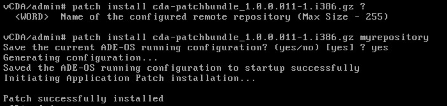
- Install the patch with the syntax "patch install cda-patchbundle_1.0.0.011-.i386.gz CDApatch2"
If you've done everything correctly..it will ask you to save your configs and will begin "Initializing Application Patch Installation." This patch seemed to take forever to update...just an FYI. Furthermore, this patch will require a system reboot.
After I applied the 4 patches, I was able to successfully use chrome/firefox to manage the CDA.
Now to try and add an active directory server!
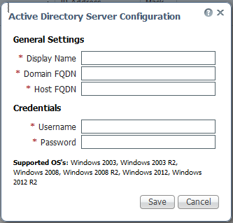
One thing to note....I tried doing this and was unable to successfully establish a connection. The live log in the CDA shows the following:

If I click on the little eye, it gives us a bit more information:

What....check the domain/username/password? I know its right..I'm using my domain admin account. Weird....onto Cisco's documentation!
Permissions Required when an Active Directory User is a Member of the Domain Admin Group
No special permission is required for the following Active Directory versions:
Windows 2003
Windows 2003R2
Windows 2008
*******************************************************************************
For Windows 2008 R2,Windows 2012, and Windows 2012 R2, the Domain Admin group does not have full control on certain registry keys in the Windows operating system by default. In order to get the CDA to work, Active Directory admin must give the Active Directory user Full Control permissions on the following registry keys:
HKEY_CLASSES_ROOT\CLSID\{76A64158-CB41-11D1-8B02-00600806D9B6}
HKLM\Software\Classes\Wow6432Node\CLSID\{76A64158-CB41-11D1-8B02-00600806D9B6}
In order to grant full control, the Active Directory admin must first take ownership of the key. To do this:
Step 1 Go to the Owner tab by right clicking the key.
Step 2 Click Permissions .
Step 3 Click Advanced .
*********************************************************************************I granted my administrator account ownership of the key and gave it full control on both of the recommended registry keys. As soon as I made this change..
P.S..this was with windows firewall OFF on the domain controller. What if we turn it back on?

SHIT BREAKS
To work around this, I created two rules on my domain controller's firewall: Allow TCP and UDP from my vCDA appliance. Yea...if this was production i'd likely want to be more granular..but I'm just being lazy.
Now that we've got the CDA linked with AD...we need to link the CDA with the WSA!
The configuration to do so is fairly simple:

Once we've done this on the CDA...we need to create an authentication realm on the WSA!

One thing worth noting: You MUST have a DNS entry for the management hostname. I didn't..and it was failing. Once I created the entry, the "Join Domain" worked successfully.
Also, the Primary Active Directory Agent is the CDA appliance---make sure the shared secrets are identical!
Now.....We need to create some identity groups under the web security manager. This will allow us to identify based on IP address or NTLMSSP. For this example, I created one policy for all NTLMSSP. This policy will reference the authentication realm we JUST created.
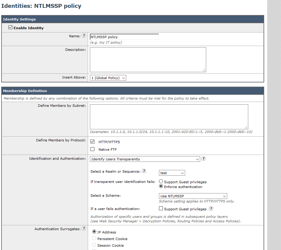
BE SURE TO HAVE IDENTIFY USERS TRANSPARENTLY
Next, we need to configure an access policy!
In advance, I created a security group called "wireless users" and created an AD account called "testwireless."

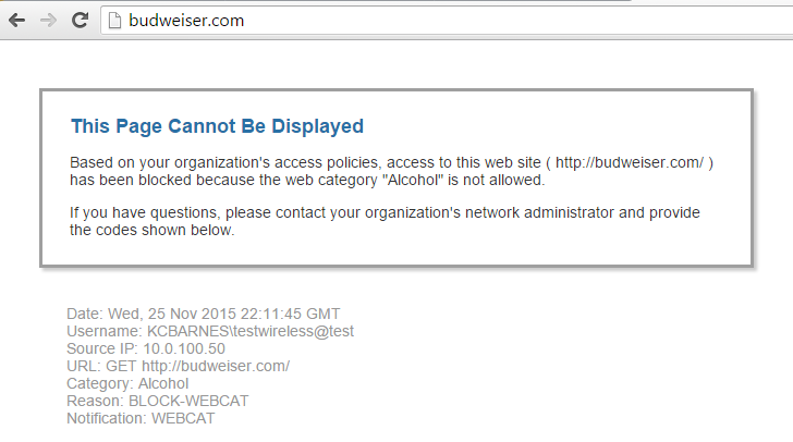
I blocked two categories for testing: Pornography/Alcohol related sites.

So let me log in on my laptop with the AD credentials I created...
Lets see if there were any mappings created?

As you can see, 10.0.100.50 maps to the username testwireless! Awesome!
Now...lets try and get to something on the internet..

Yay! It didn't break it at least...
What about the categories we blocked?

Hell YEA!!! Not only did it block it..but it let the user know that they're being tracked by username!
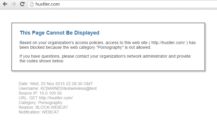
What about pornography?


NEAT!!!!!!!!!!!!!!
In advance, I created a security group called "wireless users" and created an AD account called "testwireless."

I blocked two categories for testing: Pornography/Alcohol related sites.

So let me log in on my laptop with the AD credentials I created...
Lets see if there were any mappings created?
As you can see, 10.0.100.50 maps to the username testwireless! Awesome!
Now...lets try and get to something on the internet..

Yay! It didn't break it at least...
What about the categories we blocked?
Hell YEA!!! Not only did it block it..but it let the user know that they're being tracked by username!
What about pornography?
Cool! Now for the BEST PART!!!!
Before CDA...if we wished to review the web tracking logs...all we could see were IP addresses. Since implementing CDA...we get to see usernames instead!


