Spanning-Tree Protocol (STP)
Purpose: The purpose of STP is to prevent bridging loops / broadcast storms
Because switches flood broadcasts out all interfaces in the same VLAN, except the interface in which the frames arrive, having multiple paths can cause broadcasts to circumvent the network.
Life..without STP:
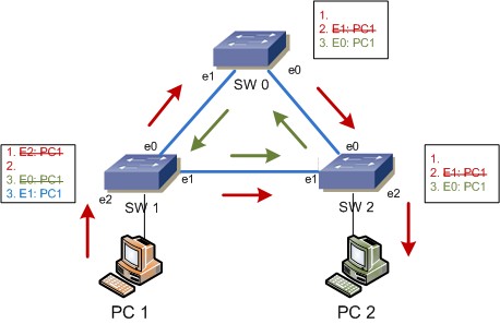
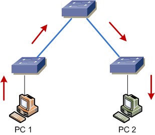
Using the example shown here, when a PC on Switch 1 attempts to communicate with a PC on Switch 2, the following happens:
- Initially, a switch knows nothing of the devices hanging off its interfaces. Therefore, when a frame is received that is destined for a MAC address unknown to the switch, the switch broadcasts the request out of every interface (except the one from which the frame entered).
- When Switch 1 receives the broadcast, it forwards the frame to both Switch 0 and Switch 2. It also adds the MAC address associated with the client to the MAC address table with the interface e2
- When Switch 0 receives the broadcast, it first adds the MAC address of PC 1 to the MAC address table, with an incoming interface of e1. It then proceeds to broadcast the frame out interface e0.
- When Switch 2 receives the broadcast, it first adds the MAC address of PC 1 to the MAC address table, with an incoming interface of e0. It then proceeds to broadcast the frame out interface e1 and e2. When PC 2 receives the broadcast, it sends back a unicast ARP reply to Switch 2. When Switch 2 receives the arp reply, it adds the MAC address associated with PC 2 to its MAC address table with an associated interface of e2.
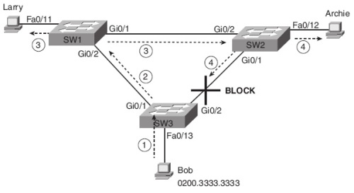
Given the scenario above, a broadcast can have a different effect than the example listen above. In this example, we will review a scenario where a broadcast storm can consume a significant part of the links' capacity.
- In this scenario, Bob will try to send an arp request to a PC that does not reside on the same broadcast domain. When SW3 receives a frame destined for 'Kyle' it broadcasts the frame to both SW 1 and SW 2.
- When SW 1 and SW 2 receive the broadcast, they also broadcast the interface out every interface, other than the one the broadcast was received on.
- Now, when SW 1 and SW 2 send out a broadcast, they are received by SW3 and SW3 will continue the broadcast. When the frame is received on int Gi02 on SW3, it will forward the frame back to SW 1, and vise verse with SW 2.
Also, as a result of the broadcast storm, MAC address table instability becomes an issue. In the example listed above, when SW 3 receives the frame from SW 1 and SW 2, SW 3 will update its MAC address table to indicate that Bob hangs off of the incorrect interface. Now, if any frame arrives at SW 3 with a destination of Bob's MAC address, SW 3 would incorrectly forward the frame which could cause yet another loop.
Now, what does spanning-tree do?
STP prevents the types of loops listed above by placing each bridge / switch port in either Forwarding State or a Blocking State. The tree structure creates a single path to and from each Ethernet segment, just like you can trace a single path in a living tree, growing tree from from the base of the tree to each leaf. By utilizing the spanning tree algorithm (STA), STP chooses the interfaces that should be placed into Forwarding State, and which interfaces should be in Blocking State.
What determines if an interface should be put in Forwarding State:
- STP elects a root switch, placing all working interfaces in Forwarding State.
- Each non root switch considers one of its ports to have the least administrative cost between itself and the root switch. STP places the least-root-cost interface, called the switch's root port (RP), in Forwarding State (All ports on root switch are considered designated ports).
- Because many switches can attach to the same Ethernet segment, the switch with the lowest administrative cost from itself to the root switch, as compared with the other switches attached to the same segment, is placed in Forwarding State.
How is the root switch elected? Switches elect a root switch based on the bridge IDs in the BPDUs. The root switch is the switch with the lowest numeric value for the bridge ID. In the event of a tie, the switch with the lowest MAC address portion of the bridge ID is the root. STP elects the root in a manner not unlike a political election. All switches claim to be the root by sending Hello BPDUs listing their own bridge ID as the root bridge ID. If a switch hears a Hello that lists a better (lower) bridge ID--that switch stops advertising itself as root and starts forwarding the superior Hello.
Now the root switch, what now? After the election is complete, only the root switch continues to originate STP Hello BPDU messages. The other switches receive the Hellos, update the sender's BID field (and cost-to-reach-the-root field), and forward the Hellos out other interfaces.
Root port, how is it elected? A switch's root port (RP) is the interface through which it has the least STP cost to reach the root switch. To calculate the cost, a switch adds the cost listed in a Hello to the STP port cost assigned to the same interface.
Electing the designated port? The designated port on each LAN segment is the switch port that advertises the lowest-cost Hello onto a LAN segment. If there is a tie, the switches break the tie based on the switch with the lower bridge ID.
Reacting to changes in the network? The root sends out a new Hello BPDU every 2 seconds by default, with a cost of 0. Each switch then forwards the hello on all DPs, after changing the cost to reflect that switch's cost to reach the root and the sender's bridge ID field is also changed. These steps will continue until something changes. If a switch stops receiving Hellos from the root, it lets the switch know something has failed, so the switch reacts and starts the process of changing the STP topology.
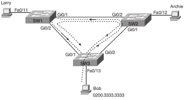
If we were to utilize STP in the previous examples: